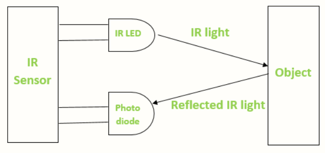
How does work IR infrared sensor Circuit Diagram IR (Infrared Sensor) is an electronic instrument that is used to detect any type of obstacle/object & it is also used to detecting the black & white colour. In this example I am showing how to use IR Sensor with Arduino Using an Infrared (IR) sensor could solve this problem together with the WiFi capability of the ESP32 microcontroller. We will program our ESP32 using the Arduino framework and create two practical IoT projects using this IR sensor. If you want to see a demo of this project then please see the below video or watch it on my YouTube channel.
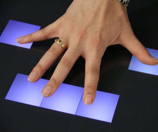
An interactive panel is any kind of digital display like touch screen TVs, touch screen displays, or touchable projections. Mostly they are running digital displays software and using different technology to recognize human interaction. There are capacitive and infrared touch screen displays and there are Lidar/sensor-based solutions like OptiTUIO.
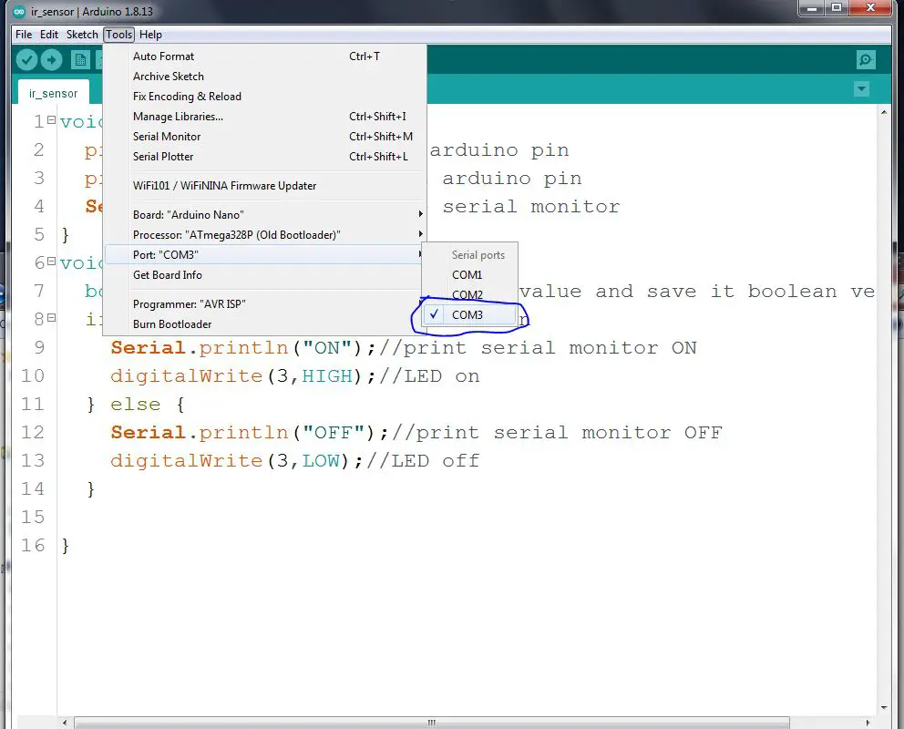
This is a example project of how to use a IR sensor with Arduino. Circuit Diagram
The Sharp IR sensor emits infrared light from its emitter. When the light reflects off an object, it returns to the sensor's receiver. The sensor then calculates the angle of the reflected light to estimate the distance. The output is an analog voltage, which decreases as the distance increases. Wiring the Sharp IR Sensor to Arduino Today we are going to talk about the IR sensor modules in this post. This sensor is the most important for making robots. I promise to present those projects in the next articles. 1st Sensor type. This sensor has four pins. The DO pin of the sensor returns a digital value and the AO pin returns an analog value.

IR Sensor Pinout. Understanding the IR sensor pinout is essential for proper wiring and functionality. Most IR sensors have three pins: VCC: Connects to the power supply (usually 3.3V or 5V). GND: Connects to the ground. OUT: Provides the output signal to a microcontroller or other device. Some IR sensors may have additional pins for features like adjustable sensitivity or onboard signal

Smart Mirror Touchscreen (with FaceID) Tutorial Circuit Diagram
In addition, the IR frame was used in order to add a touch interaction with the smart mirror. The IR frame uses a USB 3.0 peripheral to connect to the Raspberry Pi. Some IR frames also support multi-touch gestures on different Operating Systems e.g. Windows and Mac, this makes it useful for future projects. Learn Arduino in 30 Minutes (video): http://robojax.com/L/?id=135This video shows you how to use the Sharp infrared sensor to measure the distance and displa